|

|
|
|
The first installation We installed the first rotatable mast back in 1977. This mast had a height of 43 m (137ft) and carried a 3-el yagi for 7 MHz, 2 x 6-el yagi for 14 MHz, 6-el for 21 MHz and 6-el for 28 MHz. We used a 1/4-wave vertical on 3.5 MHz.
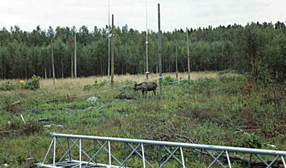
4-SQ for 3.5 MHz In 1996 we installed a new vertical for 3.5 MHz. This antenna was torn down by a moose walking across one guying point in Februari 1999.
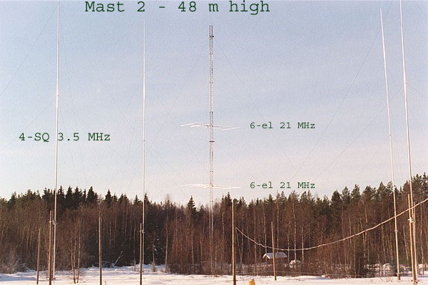
This called for some action so in the summer of 1999 we erected a 4-square for 3.5 MHz. This antenna was made moose safe since the elements as well as guying points were fitted to wooden poles. A rope was also fitted between the poles to prevent moose from entering the 4-SQ area. A moose calf did not take much notice of this as you can see below. The entire array was designed according the recommendation from COMTEK, www.comteksystems.com, and has been performing well since then.
New antennas for all amateur HF bands During the CQ WPX SSB contest 2000 one of the top guy fittings of the rotatable mast broke. A major repair was one alternative. While taking a cross country skiing trip around our 6 acres lot during the winter of 2000/2001 we took a close look at our field and the idea of erecting some new masts and more antennas emerged.
Plans were made for yagi antennas on all bands except 1.8 MHz where a yagi would be impractical. Apart from this some dipoles and vertical arrays were planned. All yagi antennas, except one, are fullsize monoband, single or stacked according to the table below.
All antennas are designed by using Yagi Analysis and EZNEC Pro, www.eznec.com. The mechanical design is our own using gamma matches on all antennas.
In all this makes 20 arrays made up of 30 antennas with a total of 137 elements! (apart from these we also use 15-el on 144 MHz and 23-el on 432 MHz)
* = Stacked by using Stack Masters from Array Solutions - www.arraysolutions.com
Feeders Three types of feeders are used:
7/8" Cellflex is used as the main feeder between the shack and the masts. Ecoflex 15 is used as jumpers at the end of the Cellflex runs. RG213 is used from the Stack Masters to the feeding points.
Some information on the Yagi antennas: (to view photos of the arrays click on the headlines below)
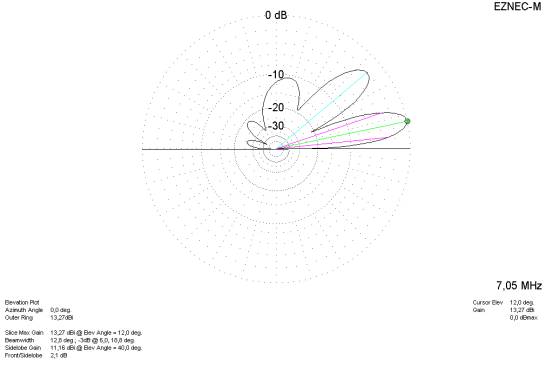
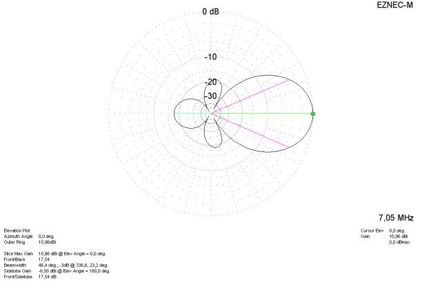
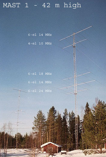
The 7 MHz yagis are reasonable sized with a 100 x 100 mm aluminium boom of 14 m. The elements are tapered from 50 mm (center) to 12 mm (tip). The first yagi was installed in 2000 and the second in 2003. The yagis have performed as expected with a lot of DX in the log. The top antenna is installed at about 48m (157 ft). The lower antenna is installed at 24 m (78 ft) height. The stack can be switched between the lower and upper or both.
Below is the pattern of the upper antenna shown:
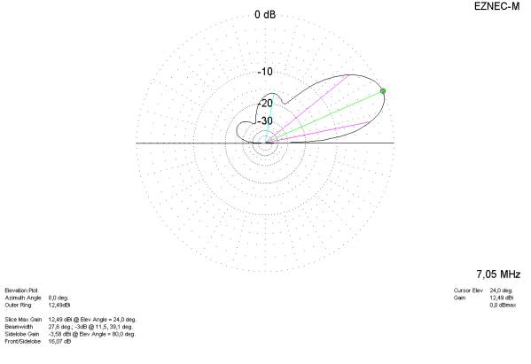
Below is the pattern of the lower antenna shown:
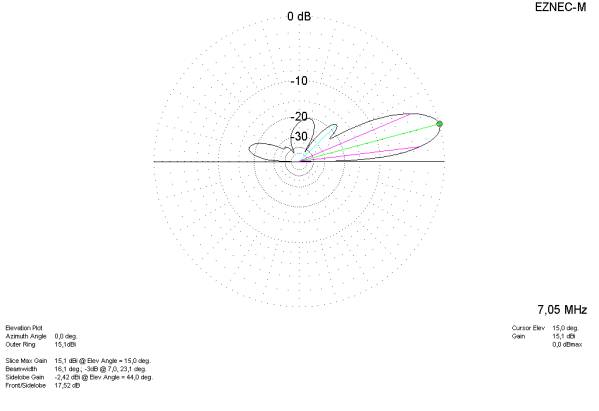
Below are the patterns of the stacked antennas shown:
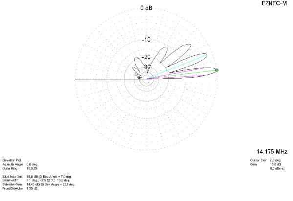
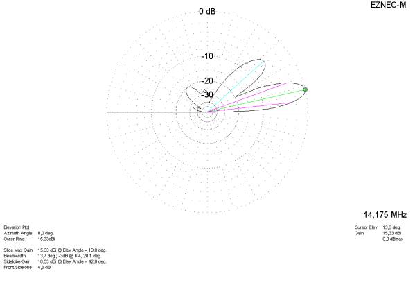
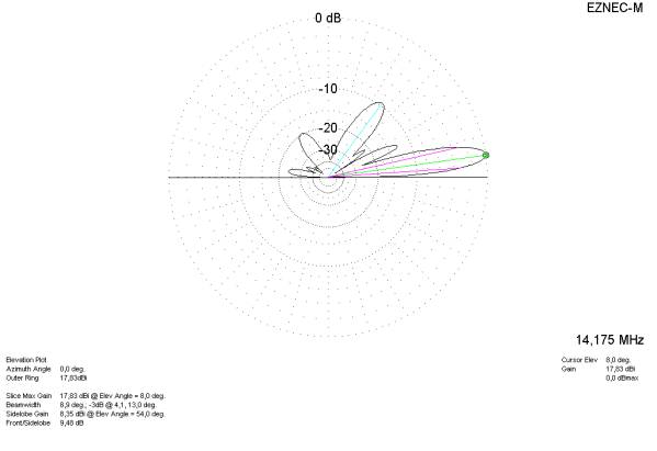
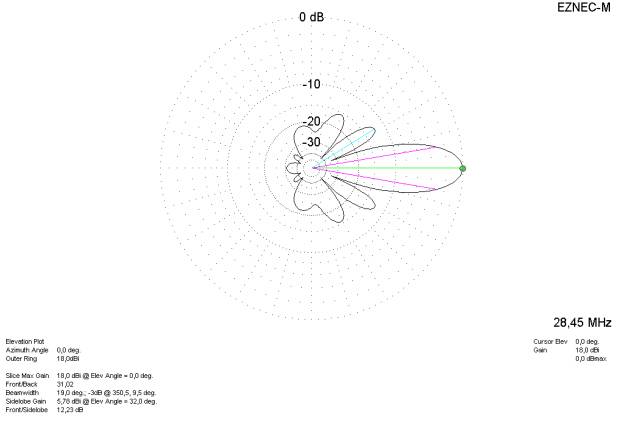
The 14 MHz yagis are using 75 and 60 mm tubes as boom. The elements are tapered from 31 mm (center) to 12 mm (tip). The top antenna is installed at about 42 m (138 ft). The lower antenna is installed at 22 m (72 ft) height. The stack can be switched between the lower or upper or both.
Below is the pattern of the upper antenna shown:
Below is the pattern of the lower antenna shown:
Below are the patterns of the stacked antennas shown:
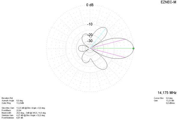
The 21 MHz yagis are using 60 and 50 mm tubes as boom. The elements are tapered from 28 mm (center) to 12 mm (tip). The two yagis were installed in 2000 but due to the winter arriving up here in the north with snow and cold temperatures, the coaxial cables and rotator were not connected until 2001. The top antenna is installed at about 27 m (89 ft). The lower antenna is installed at 15 m (49 ft) height. The stack can be switched between the lower or upper or both.
Below is the pattern of the upper antenna shown:
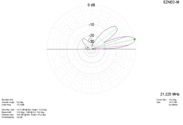
Below is the pattern of the lower antenna shown:
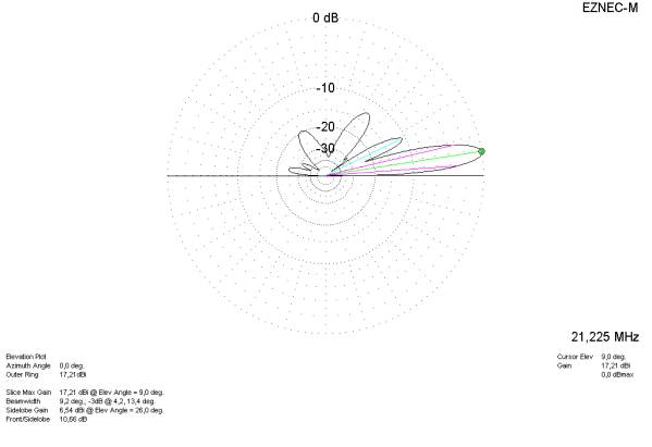
Below are the patterns of the stacked antennas shown:
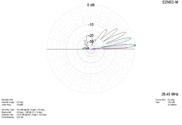
3x(2x6-el) 28 MHz Yagi (Mast 3) The 28 MHz yagis are using 60 and 50 mm tubes as boom. The elements are tapered from 28 mm (center) to 12 mm (tip). The six yagis were installed in pairs of two and two. A 125 mm beam with a length of 10 m (32.8 ft) is used as the horizontal stacking beam. The horizontal stacking distance as well as the vertical one is 9.66 m (31.69 ft). A 1000 mm long 75 x 5 mm tube is used for vertical fitting of each antenna. The 2 antennas at each level are permanently stacked by using a Mini StackMatch. One coax from each Stack Match is than connected to the Stack Master.
These were the antennas that were top priority before the winter 2000. All were in working shape just in time for the CQWW in October 2000. The antennas have worked better than expected during the CQWW (CW & SSB), ARRL (10m & DX) and CQWPX SSB in 2000/2001. In all these contests 7S2E has been aired as single op, single band entries.
About 200 countries have been worked and nice pileups have been encountered. The stacking has been compared on air with some stations to ensure that the transmitted signal shows the same improvement as the signal received does. Reports have been very consistant and always show the same result. Once used to the narrow beam width it is easy to find the stations in down town New York.
The top antennas are installed at 29.98 m (98.46 ft). The middle antennas are installed at 20.32 m (66.66 ft). The lower antennas are installed at 10.66 m (34.97 ft) height. In all 7 different combination can be switched between these pairs.
Below is the pattern of a single antenna shown:
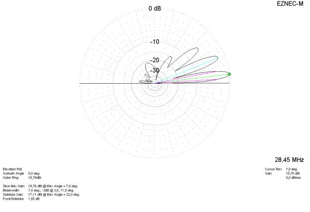
Below is the pattern of the two upper antennas shown:
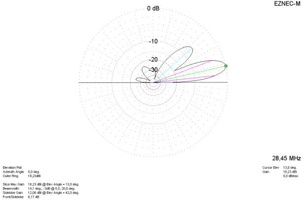
Below is the pattern of the two middle antennas shown:
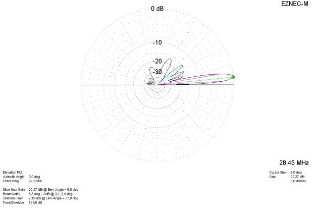
Below is the pattern of the two lower antennas shown:
Below are the patterns of the 6 stacked antennas shown:
|

