|

|
|
|
Once we decided to erect new rotatable masts there were some things to take into consideration and improve from the previous mast we had installed. 1. The masts should withstand larger loads. 2. The guy attachments in the mast had to be changed ( this was what failed on the old mast). 3. The mast base with bearing should be changed to avoid using a chain driven motor. 4. Mast foundation with the mast about 1m (3.3 ft) above ground to avoid snow. 5. Make a very simple and reliable direction indicator. 6. Make provision for lubrication of base and guy attachments. |
| 1. Larger
Loads
To enable the masts to carry larger loads we designed the sections with 60 x 5 mm S355 steel tubing and diagonals made of 20 mm (0.77") solid rods. The width of the section is 600 mm (23.6") center to center and the length of a section is 6 m (19.7 ft). The sections are hot dip galvanized to 100 microns to prevent rust. To enable access to the antennas, one side of the frame work have horizontal bars for climbing the mast. |
| Outline of Sections
|
| 2. Guy
Attachments
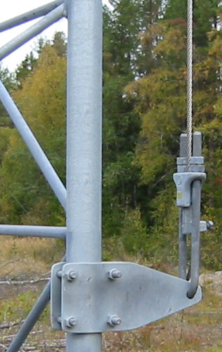
The guy attachments are designed to be able to take care of the load from the guys despite the position of the mast. A mast with a normal ring width (about 60 mm) has its weakest point when the guys are facing the sides of the mast. This called for a larger than normal plate to be used as the lower guy ring (the one fixed to the mast). The plate is 205 mm (8") wide and 20 mm (0.79") thick. The upper ring (the one fitted to the guy wire) is also 20 mm thick but only 67 mm (2.64") wide. This plate is also fitted with inlets for lubrication. All guy attachments are hot dip galvanized to 100 microns. With this arrangement the guy attachment has to be fitted between 2 sections. Top view of the lower plate.
The guy wires are fitted to the guy attachment by using slack pullers. The hooks that connect the slack pullers are made so that the force created by the wires are directed straight through the bearings of the guy ring. Two holes are made in each hook. One for the lower and one for the upper guy. The hook is bolted to the upper guy attachment ring. Separate larger hooks were made for the top guy of mast 2.
View of the guy attachment hook.
Maintenance The guy wires are tightened to about 10% of the breaking load. Typical for for 68 mm2 7-strand guy wire is 8.4 kN. Two theodolites are placed 90o apart to check verticality when straightening the masts and after one year we checked the masts again and than a check every fifth year is enough. Once a year all guy anchors and some bolts should be checked as well as a general visual check of any rust or damage. If rust can be found zink rich paint is applied after a proper brushing of the damaged area. All bolts in the masts are tightened to its proper moment.
Our old rotatable mast had the bearing very close to the ground and just above the bearing was a welded sprocket. This was driven by a chain from the motor. The construction had several draw backs.
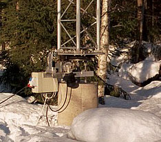
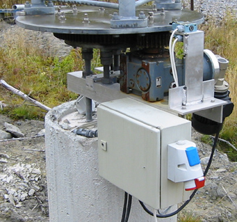
To get rid of all the problems of the old mast we decided to completly change the mast base design. First of all we raised it about one meter (3.3 ft) above the ground. Secondly we made a new base bearing solution by using a Rothe Erde Large-Diameter Antifriction Bearing available on the market. This bearing allowed for a standard gear to be connected directly to it. Four M30 threaded rods are holding the mast to the concrete foundation. The motor and worm gear assembly as well as the electronic box are connected to these rods by angular extrusions . The end stops that activates the limit switches are fitted on the plate that holds the mast section. Since the mast is operated by 380 VAC 3-phase we also fitted power plugs for 1- and 3-phase AC to the electronic box. This is very handy since electric tools can be connected at the base of each mast.
The Mast Base of Mast 1
The ground where the masts are fitted is hard clay mixed with stones. The foundation is made up of two parts first a square base 2 x 2 m (6.6 x 6.6 ft) and 0.5 m (1.64 ft) thick. On top of this is a 2 m high concrete filled tube placed. The base is reinforced with 10 mm rods.
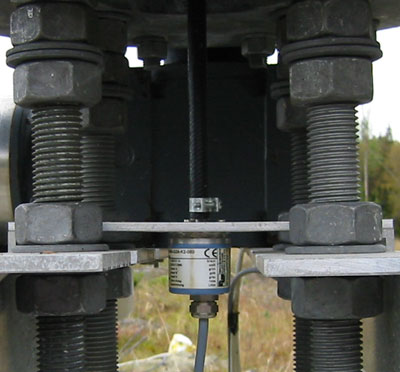
5. Rotator and Direction Indicator The old mast had an indicator with a 10-turn potentiometer and an analog instrument. This worked fairly well but had to be calibrated quite often due to slack in the transmission from the mast.
The new masts have been fitted with puls indicators that are calibrated in degrees. In the shack is a controlbox where the wanted direction in degrees is tapped in with a thumb wheel. A switch is then turned clock- or counter clockwise pending on the direction and when the mast has rotated to the preset direction it stops. The pulse indicator is fitted in the middle of the center plate at the bottom of the mast. Then it connects to the electronic box at the mastbase.
The rotator itself is a 3-phase electric motor connected to a planitary gear which is connected to a wormgear. This wormgear connects to the Rothe Erde Large-Diameter Antifriction Bearing. Mast 1 and 3 turns 360o in 2 minutes and Mast 3 turns in 3 minutes.
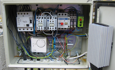
To prevent the relays in the electronic box from freezing a small thermostat operated heater is fitted inside each electronic box. The heaters are set to operate below +5 centigrades. Another safety feature is a delay of the relays once the mast has been rotated. This allows for a 15 second delay before the mast can be rotated in any direction again. This way the movement of the mast stops, thus not causing too much strain on it. The rotators are made from standard electric components and very cost efficient.
6. Lubrication Inlets for lubrication are fitted to the upper part of the guy ring as well as the base bearing. The gear at the motor is lubricated by applying grease with a brush. The lubrication of the masts are checked every year. If needed a multi purpose grease is used.
All masts are fitted with a stainless steel wire Swelock Fall Guard System.
Sofar the masts have been operating without any major problems.
|